STP (Spanning Tree Protocol) is a Layer-2 protocol that builds a loop-free network topology. Only one active path can exist between two stations in order for them to function properly. STP is a Network Protocol (Layer2) and has a Standard of IEEE 802.1D/W/S/Q, Cisco (Def on Cisco=PVST). Its function is to prevent Layer2 Loops within a network topology, adapt to network changes and failures. The STP Algorithm was designed by Radia Perlman. Spanning Tree Protocol has a Multicast Address of 01:80:C2:00:00:00, 01:00:0C:CC:CC:CD (Cisco’s PVST). There are 5 STP port states and 3 RSTP port states. Likewise, there are 3 STP Port roles and 4 RSTP port roles
Features of STP (Spanning Tree Protocol)
IEEE protocol numbered 802.1d (release 1988) and it is a Layer2 protocol that builds a loop-free topology. It is usually enabled on Layer-2 Switches by default. The roles are elected based on Bridge ID (Bridge ID = Priority + MAC). There are multiple types of STP (PVST, RSTP, MST, …) and STP Ports have 5 states (Disabled, Blocking, Listening, Learning, Forwarding)
Why do we need STP (Spanning Tree Protocol)?
If there is more than one path between two switches:
Forwarding tables become unstable
- Source MAC addresses are repeatedly seen coming from different ports
Switches will broadcast each other’s broadcasts
- All available bandwidth is utilized
- Switch processors cannot handle the load
If there is more than one path between two switches:
– Forwarding tables become unstable: Source MAC addresses are repeatedly seen coming from different ports
– Switches will broadcast each other’s broadcasts: All available bandwidth is utilized & switch processors cannot handle the load
Without STP a LAN with redundant links would cause Ethernet frames to loop for an indefinite period of time, Broadcast Storms, Multiple frame transmission
With STP enabled, some switches block ports, so that these ports do not forward frames

STP Bridge ID (Switch ID)
Every Switch (Bridge) participating in an STP network is assigned a numerical value called Bridge Priority (or Switch Priority). It is a 64-bit (8-Byte value) which consists of three parts as shown below:
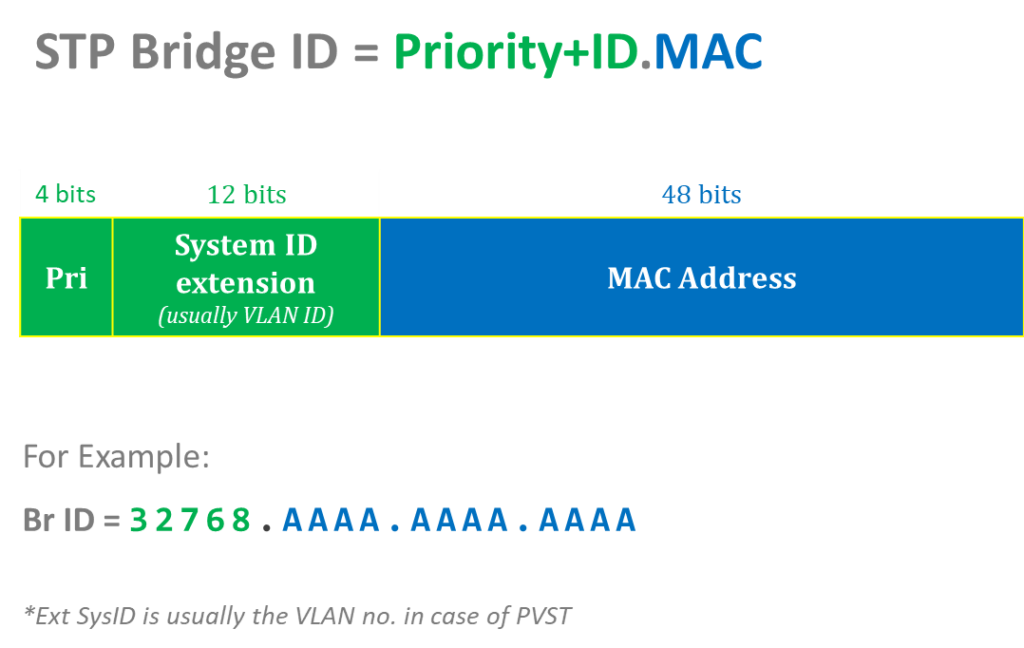
Examples of STP Bridge ID
SW1#show spanning tree
VLAN0001
Spanning tree enabled protocol ieee
Root ID Priority 32769
Address 0030.A3CA.4B33
Cost 19
Port 2(FastEthernet0/2)
Hello Time 2 sec Max Age 20 sec Forward Delay 15
Bridge ID
Priority 32769 (priority 32768 sys-id-ext 1)
Address 00E0.F955.996D
Hello Time 2 sec Max Age 20 sec Forward Delay 15 sec
Aging Time 20
Br ID for VLAN1 is = 32769.00E0.F955.996D
VLAN0010
Spanning tree enabled protocol ieee
Root ID Priority 32778
Address 0030.A3CA.4B33
Cost 19
Port 2(FastEthernet0/2)
Hello Time 2 sec Max Age 20 sec Forward Delay 15 sec
Bridge ID Priority 32778 (priority 32768 sys-id-ext 10)
Address 0000.0000.1111
Hello Time 2 sec Max Age 20 sec Forward Delay 15 sec
Aging Time 20
Br ID for VLAN10 is = 32778.0000.0000.1111
STP Operation
The following below illustrates how STP operates by creating a loop-free topology by restricting certain interfaces:
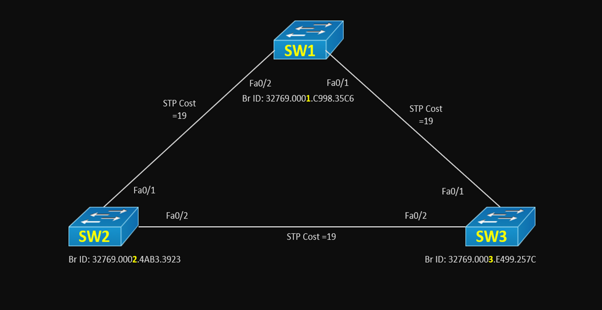
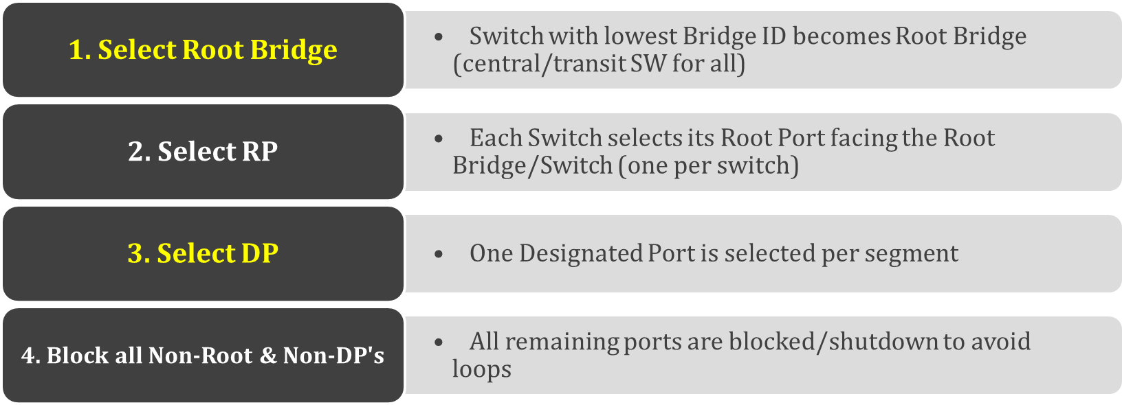
Root Port election
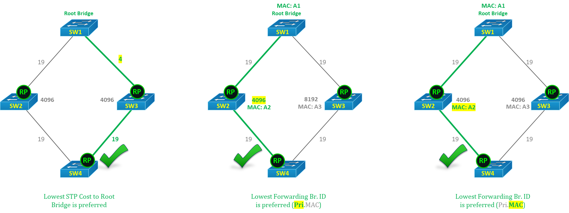
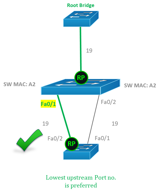
Root Port Election Rules (criteria) are:
- The lowest STP Cost towards Root Bridge is preferred
- The lowest forwarding upstream Bridge ID (Priority+SysID.MAC) is preferred
- Lowest forwarding upstream Port no. is preferred
Examples of Root Port election
The following indicates the Root port election:
Designated Ports election
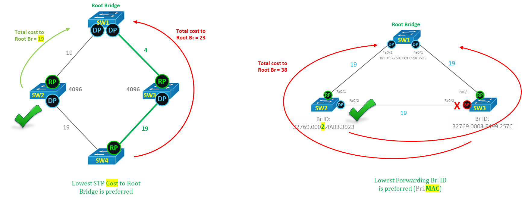
Designated Port Election Rules (criteria) are:
- All ports on Root are always DP (Designated Ports)
- All ports that are on the link with another side as RP are always elected as DP
- The lowest STP Cost towards Root Bridge is preferred
- The lowest Local Bridge ID (Priority+SysID.MAC) is preferred
- Lowest forwarding Local Port no. is preferred
Examples of Designated Port election
The following is an example of a Designated port election:
Modifying the default STP Root Bridge election
We can modify the default topology & force any Switch to become the Root for any VLAN (in PVST mode) or for all VLANs in two ways:
- Manually make a Switch as Root Bridge using the command
SW2(config)#spanning-tree vlan 20 root primary
SW3(config)#spanning-tree vlan 30 root primary
- Lower the Bridge Priority to force a Switch to become the Root Bridge
SW2(config)#spanning-tree vlan 20 priority 4096
!(any priority less than default 32768)
SW3(config)#spanning-tree vlan 30 priority 4096
STP BPDU (Bridge Protocol Data Units)
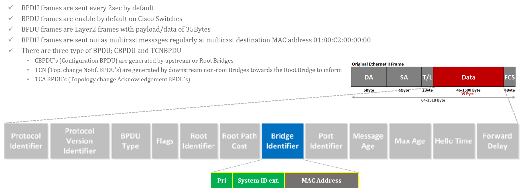
BPDUs (Bridge Protocol Data Units) are STP data frames through which switches share STP information with each other to create a loop-free topology. When a switch receives a BPDU packet it uses a mathematical formula called the Spanning tree algorithm to determine which port need to be shut down if any loop occurs
Features of STP BPDU (Bridge Protocol Data Units)
Below are the features of STP BPDU:
STP (Spanning Tree Protocol) Versions
The following are the STP versions available:
- STP: This is the original protocol defined by IEEE 802.1D in 1988. It creates a single spanning-tree over a network
- PVST/PVST+: This is a Cisco proprietary version of STP & allows a separate instance of STP for each individual VLAN
- RSTP: RSTP provides for faster convergence of STP topology by skipping some port states. It comes with faster convergence features enabled by default (portfast, uplink fast, …)
- MST: MST gives us a choice of mapping vlans to MSTP instances (instead of one STP for each VLAN like PVST)


STP (Spanning Tree Protocol) Port Roles
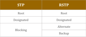
There are 3 STP port roles, which include Root, Designated, and Blocking. The table below shows STP Port Roles:
STP (Spanning Tree Protocol) Port states
STP port states are 5 in number and they are Disabled, Blocking, Listening, Learning and ForwardingThe table indicates the STP port states that are available:

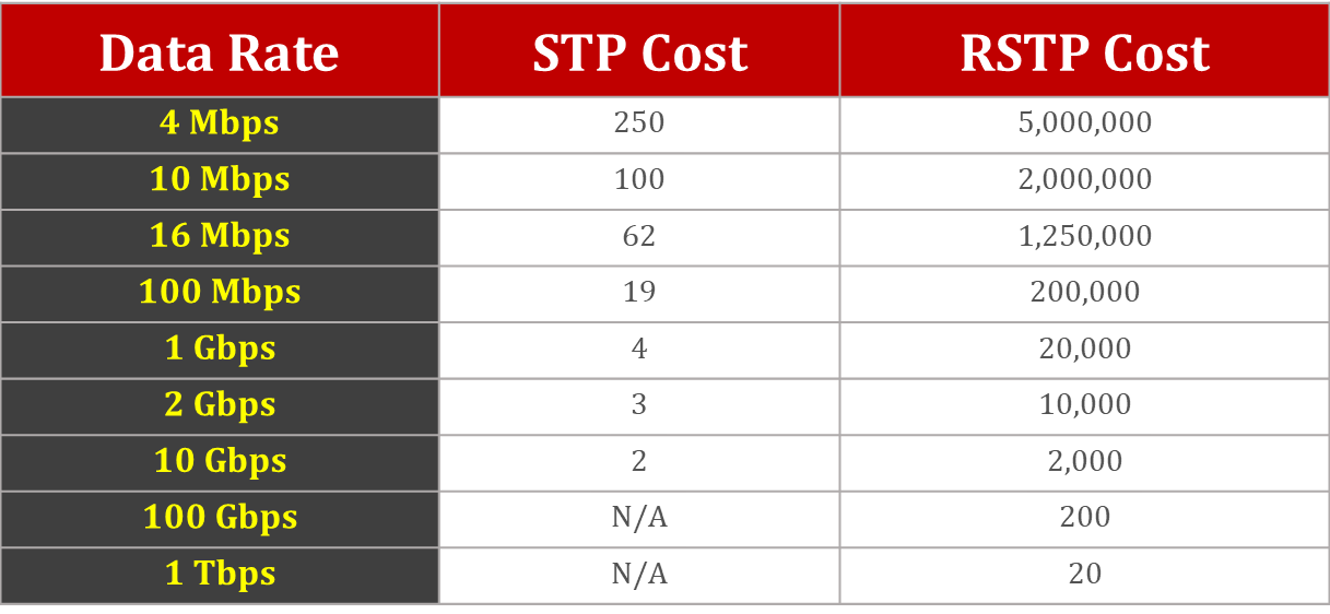
STP (Spanning Tree Protocol) Link Costs
The table below shows the STP link costs:
STP (Spanning Tree Protocol) Timers
Below is the table showing STP Timers:

STP Advanced Features (STP Toolkit)
The following are the STP advanced features (STP Toolkit):
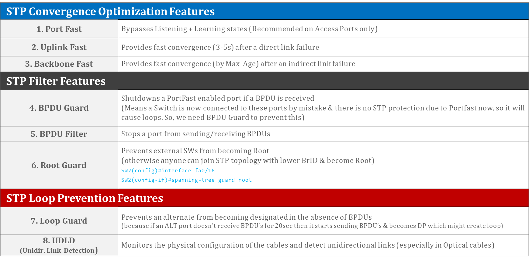
Below are the STP Convergence Optimization Features:
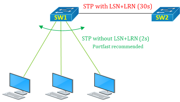
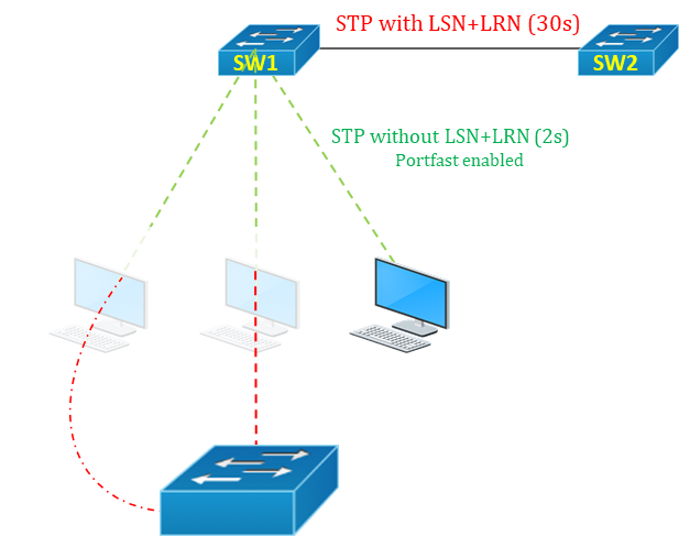
- Port Fast: It bypasses the Listening & Learning states (saves 15s+15s). It is recommended to be enabled on Access Ports only to avoid loops
Port Configuration:
Option1: Global Level (enable on all access ports)
SW1(config)#spanning-tree portfast default
Option2: Interface Level
SW1(config)#interface fa0/1
SW1(config-if)#spanning-tree portfast
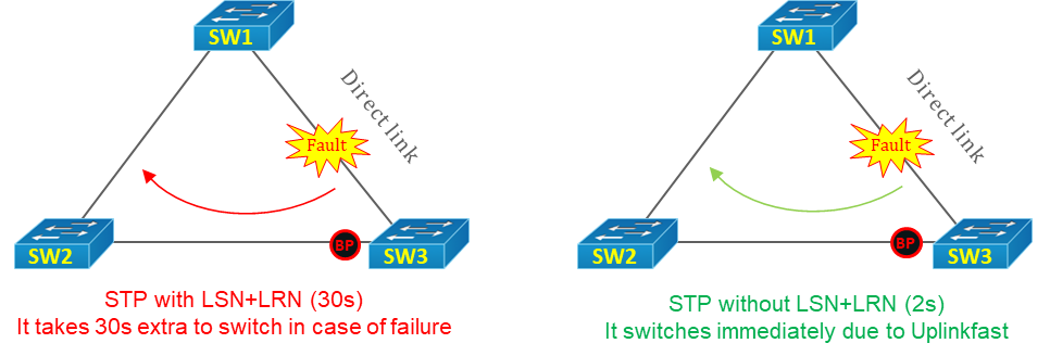
2. Uplink Fast: Provides fast convergence (3-5s) after a direct link failure
Uplink configuration:
SW1(config)#spanning-tree uplinkfast

3. Backbone Fast: Provides fast convergence (by Max-Age) after an indirect link failure
Backbonefast configuration:
SW1(config)#spanning-tree Backbonefast
4. BPDU Guard: Shutdowns a PortFast enabled port if a BPDU is received (means a Switch is now connected to these ports by mistake & there is no STP prevention due to Portfast now, so it will cause loops. So, we need BPDU Guard to prevent this)
BPDU Guard configuration:
Option1: Global Level (enable on all access ports)
SW1(config)#spanning-tree portfast bpduguard default
Option2: Interface Level
SW1(config)#interface fa0/1
SW1(config-if)#spanning-tree bpduguard enable
5. BPDU Filter: Enables back STP (disables Portfast) on a PortFast enabled port if a BPDU is received (the same function as BPDU Guard but disables Portfast instead of shutting down the port)
BPDU Filter configuration:
Option1: Global Level (enable on all access ports)
SW1(config)#spanning-tree portfast bpdufilter default
Option2: Interface Level
SW1(config)#interface fa0/1
SW1(config-if)#spanning-tree bpdufilter enable
You might also be interested in our free Online Quizzes on all IT topics including Cisco CCNA, Cyber Security, Python Programming, Linux & Ethical Hacking:
Free Online Quizzes (Best for Cisco CCNA, Huawei HCNA, N+)
You can also view free study notes (Cheat sheets) for long term memory:
Networkwalks Summary Cheatsheets
 STP (Spanning Tree Protocol) is a Layer-2 protocol that builds a loop-free network topology. Only one active path can exist between two stations in order for them to function properly. STP is a Network Protocol (Layer2) and has a Standard of IEEE 802.1D/W/S/Q, Cisco (Def on Cisco=PVST). Its function is to prevent Layer2 Loops within a network topology, adapt to network changes and failures. The STP Algorithm was designed by Radia Perlman. Spanning Tree Protocol has a Multicast Address of 01:80:C2:00:00:00, 01:00:0C:CC:CC:CD (Cisco’s PVST). There are 5 STP port states and 3 RSTP port states. Likewise, there are 3 STP Port roles and 4 RSTP port roles


 Below are the STP Convergence Optimization Features:


